Introduction
A wrench is a mechanical tool used to provide grip and mechanical advantage in applying torque to turn objects and is often used for fastening the fasteners like fasteners by applying torque on them. The word wrench originally means turning or twisting. The wrench is also commonly known as a spanner. The word “spanner” refers to a tool which is used in a firearm and is also derived from the same word “spanner”, which means to join, fasten, or connect.
There are many different types of spanners available which include:
- open-ended spanners
- ring spanners
- open-ring spanners
- scaffolder spanners
- flogging spanners
- shifter spanners and many others.
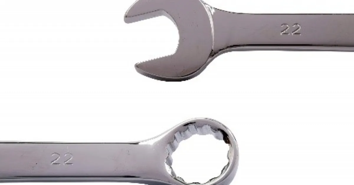
Wrench being used for Finite Element Analysis Out of all the above mentioned spanners a combination spanner also called as an open-ring spanner is a multi-purpose tool which is also a double-ended tool with one end being an open-end wrench or an open-ended spanner used for tightening and loosening in small spaces and the other end being like a box-end wrench or a ring spanner used for leverage (strength for opening bolts) and a firm grip around nuts and bolts. These ends of a combination spanner generally fit the bolt of the same size and is being use for the finite element analysis.
All these wrenches come in different standards, which include:
- Standard Combination Wrenches
- Metric Combination Wrenches
- Standard Flare Nut Wrenches. The most used standard in India is Metric Combination wrenches whose sizes start from 6, 7, 8, 9, and so on till 32.
The spanner or wrench in these days are being utilized all over the world for fastening the fasteners. This likewise gave many thoughts in making numerous different devices like:
- church-key also called a container opener used for opening vessel tops of the jug
- sardine can key used for opening canned food items
- paint can opener used for opening
- window wrench and so on.
3D modelling of parts / Assembly
-
The spanner or wrench is a mechanical instrument, basically a tool and is utilized by everyone around the globe for securing the fasteners. This confirmation sees to that the spanner satisfies all the geometrical conditions needed and resilience.
-
At that point as indicated by the particular, the demonstration of the spanner or wrench is finished utilizing the SIMULIA ABAQUS which is a Computer-Aided Design engineering software and the same software is used for performing the Finite Element Analysis (FEA).
-
Once the 3D model of the spanner is made, the material is assigned. After that, the mesh analysis is performed.
-
Mesh Analysis is done so that the complex model made is divided into very small elements and then these small elements are solved resulting in the final value.
-
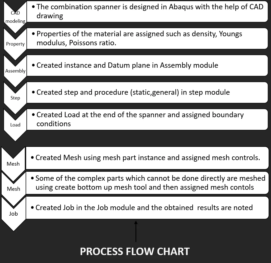
The mesh affects the speed of simulation, accuracy, and convergence. The flow chart below shows the entire process carried out in the simulation of the wrench.
-
After meshing is complete, the boundary conditions are assigned to the meshed model. In addition, the problem is solved to get the results on stress distribution, deformation, and principal strain.
Solid modelling
-
The solid modelling of the wrench or spanner can be designed with many CAD packages, out of which SIMULIA ABAQUS developed by Dassault Systems, is used here in the making the design.
-
The model is created by using simple commands in SIMULIA ABAQUS like sketch, extrude, extrude cut etc.
-
The material used in here for the manufacturing of spanner or wrench is Structural Steel which has considerably a good specific strength.
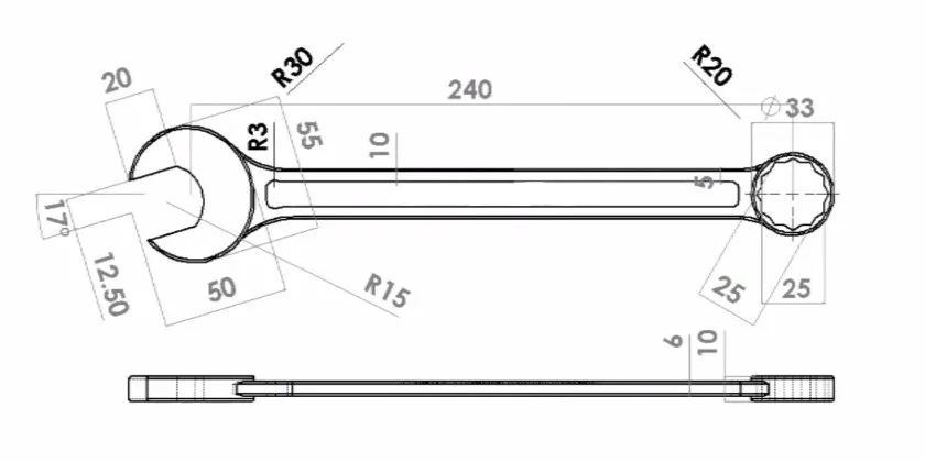
- These dimensions were considered standard for manufacturing and manufactured accordingly to perform the Finite Element Analysis.
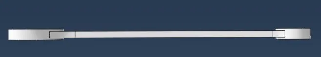
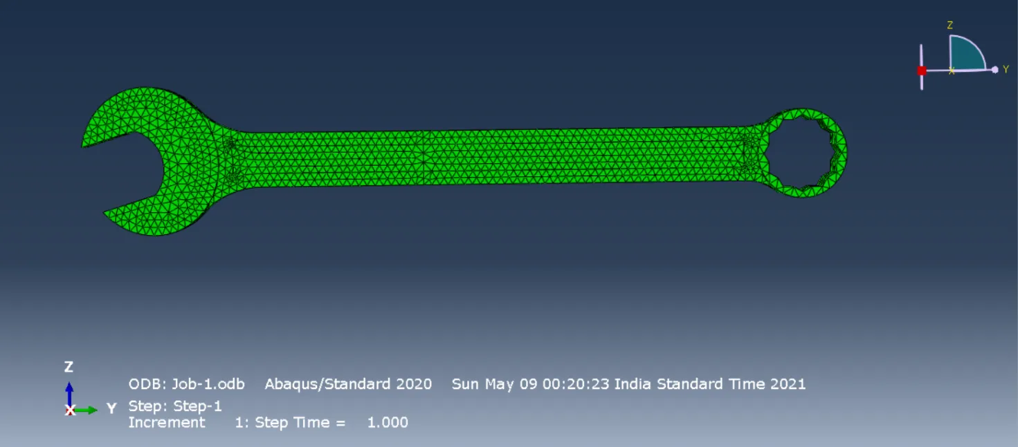
Top view of the modelled spanner or wrench
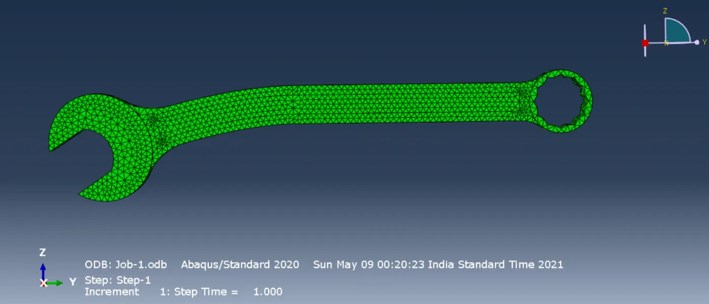
Side view of the modelled spanner or wrench
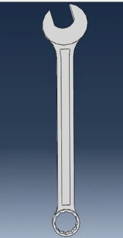
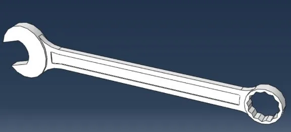
Isometric view of the modelled spanner or wrench
- The material used for manufacturing spanner or wrench is structural steel. The structural steel is easily available, fire-resistant, and ductile. It also has good corrosion resistance and is a good scratch resistant.
| Material | Structural Steel |
|---|---|
| Density | 7850 kg/mm³ |
| Young’s Modulus | 210 GPa |
| Poisson’s Ratio | 0.3 |
- This above table shows the mechanical properties of the material being used in modelling of the wrench or spanner.
Analysis of Wrench
-
Now the 3D model made of the structural steel material is assigned to the model section.
-
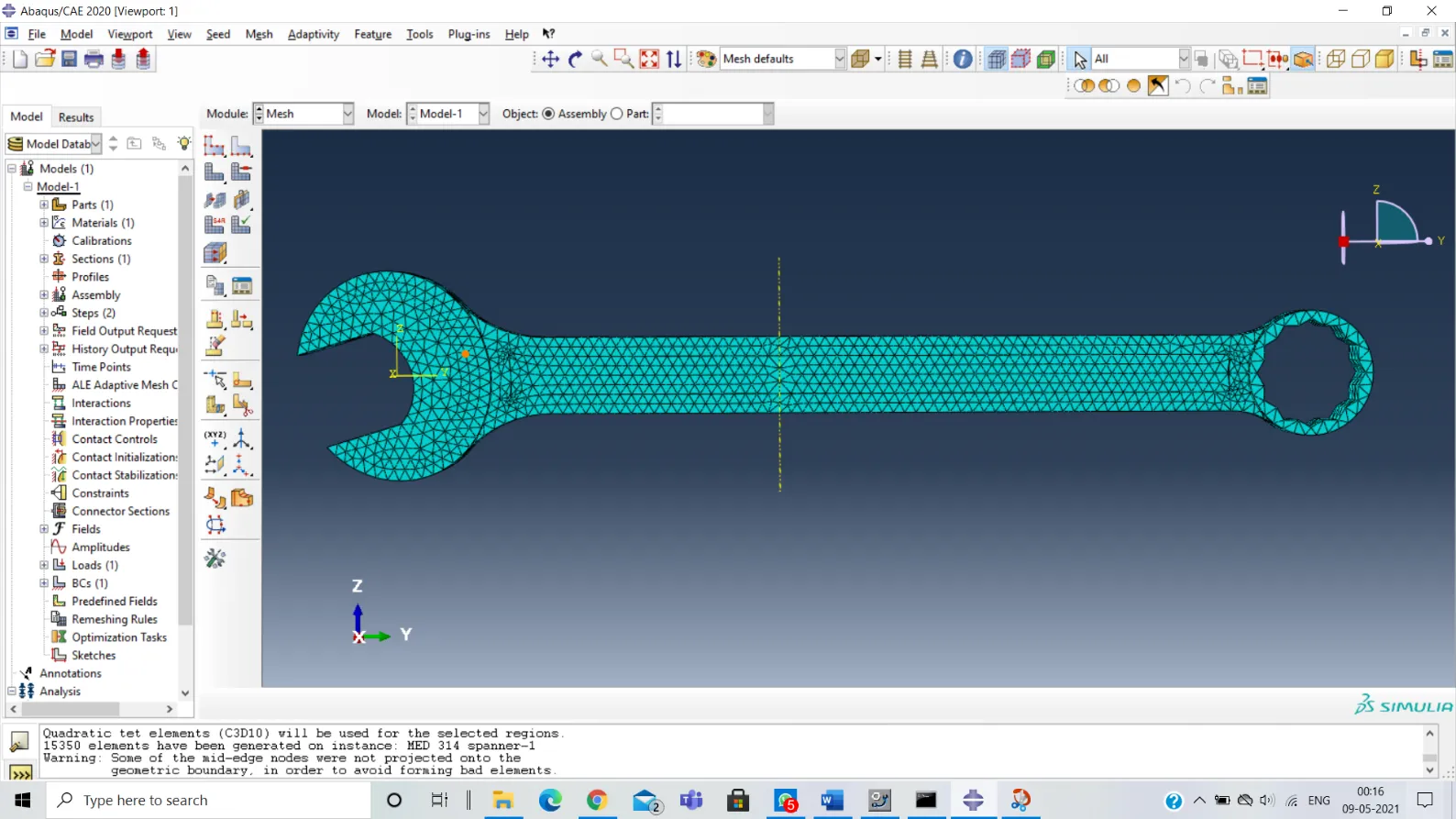
In this analysis we firstly mesh the wrench and make sure that the continuous geometric space between the elements of the object is broken down (to thousands or more) to properly get a perfect specific analysis of the body.
-
The figure below shows the meshed model of the Wrench.
-
The material used is Structural Steel. However, load conditions are like, the fixed support is provided at the open end (applied at the open end) of the wrench or spanner. The load is exactly applied at the box end of the spanner.
-
The mesh performed for this model is the tetrahedral mesh element of different sizes. The element is of C3D10 Quadratic tet elements, and it contains at most 15350 elements. And then job is submitted for the analysis. The post-process for the analysis is done.
Result and Discussions
After the analysis completes and the post processing is also complete. The output values obtained are:
- Stress Distribution
- Deformation and
- Principal stress.
- All these factors are taken into consideration and the results or the output conclusions are drawn.
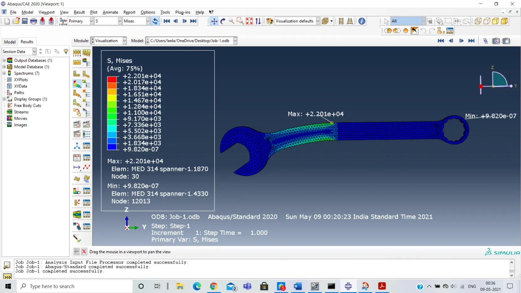
Stress Distribution
The below figure shows the stress distribution of the combination spanner. Due to the application of the load in the box end of the spanner it shows the locations of maximum and minimum stresses developed.
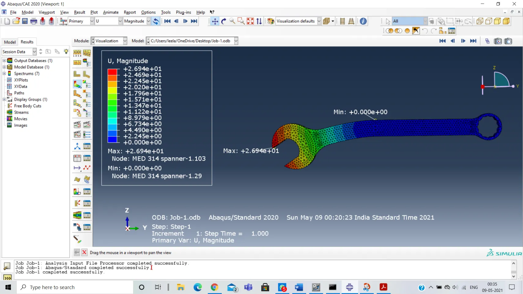
Deformation
The below figure shows the total deformation obtained in the combination spanner and locations of maximum and minimum stresses developed.
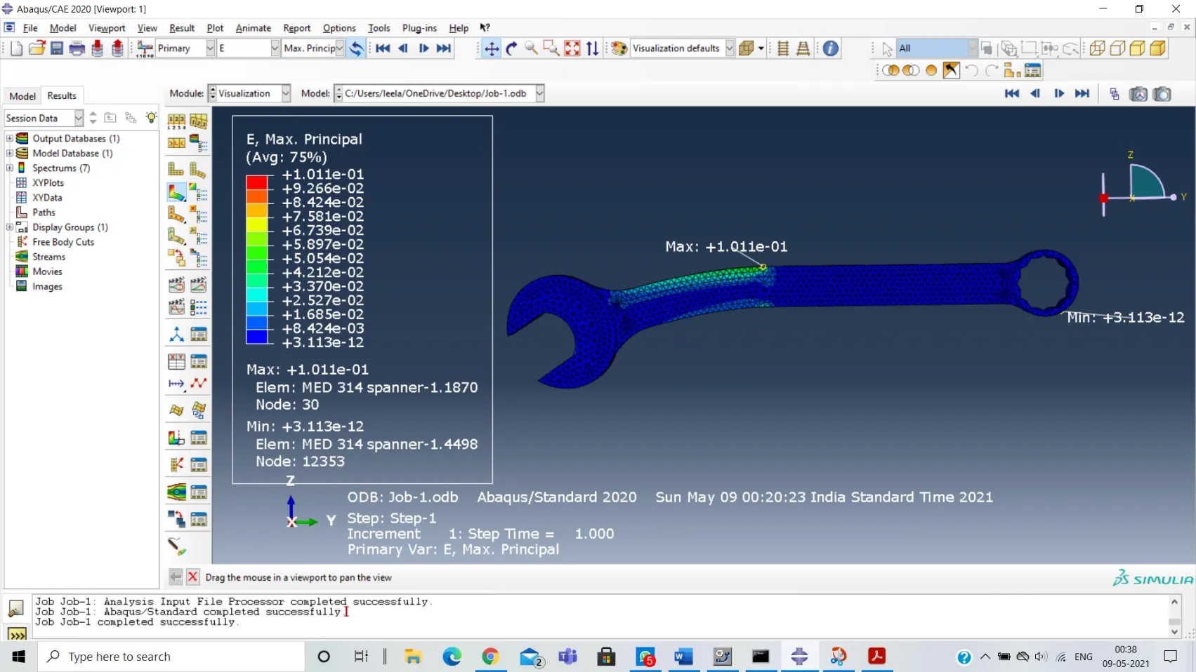
Principal Strain
The figure below shows the maximum Principal strain obtained for the combination spanner and shows the locations of maximum and minimum principal stresses developed.
Result
| Material | Von - Mises stress | Total Deformation | Maximum Principal Strain |
|---|---|---|---|
| Structural Steel | 2.201 X e4 | 2.694 x e1 | 1.011 x e-1 |
- The table above shows the various elements such as stresses, strains and deformations in the body of the wrench made of structural steel.
Structure before deformation (Before analysis)
Structure after deformation (After analysis)
Concluding Remarks
-
Hence the construction of the CAD design was successful and the analysis performed gave out the result as shown above.
-
However, the material used can be replaced and many other materials can be taken such as Cobalt-Chromium (Co-Cr alloy).
-
Hence the model prepared and analysis done shows the characteristics of the combination wrench and the maximum loads that can be given to it. Under various stresses and strains the following results describe all the characteristics of the wrench.